A ground investigation on a sloped site off Huddersfield Road recently revealed a buried sandstone channel at 14 metres depth that had not appeared on any historical mining abandonment plan. The anomaly was mapped using a 24-channel seismic refraction spread and inverted with ray-tracing tomography, which showed a sharp velocity contrast from 1,800 m/s in the overlying glacial till to 3,200 m/s in the competent rock. Seismic tomography (refraction/reflection) is routinely applied across Barnsley to resolve these subsurface ambiguities, particularly where Coal Measures strata, made ground, and Quaternary drift interleave in ways that conventional borehole logs cannot capture alone. The method delivers a continuous P-wave velocity model that supports depth-to-bedrock mapping, rippability assessment, and fracture-zone identification in advance of piling or excavation. When the target depth exceeds 30 metres, the refraction survey is combined with a MASW profiling line to constrain the shear-wave velocity structure and derive Vs30 for seismic site classification under Eurocode 8, while deeper reflection processing can image strata beyond 100 metres for tunnel or deep-basement feasibility studies.
Tomographic inversion turns a set of first-arrival traveltimes into a continuous velocity cross-section, revealing hidden faults, buried mine entries, and the true bedrock profile beneath Barnsley's complex drift geology.
Local ground factors
Barnsley’s built environment sits on a legacy of deep and shallow coal mining that dates from the medieval period and intensified through the 19th and early 20th centuries. The Coal Authority holds records of over 40 mine entries within the metropolitan borough, yet many unrecorded shafts and bell pits remain, particularly in the older workings around the town centre and the Dearne Valley corridor. Seismic refraction tomography provides a rapid, non-intrusive method of scanning a development footprint for the characteristic low-velocity signature of collapsed or backfilled shafts — typically a V-shaped velocity sag that disrupts the otherwise continuous bedrock refractor. Missing these features during a desk-study-only phase can lead to sudden collapse during excavation, differential settlement under foundation loads, or methane migration pathways into buildings. The risk is amplified on the sandstone escarpments west of the town, where cambering and valley bulging produce tension cracks and rotated blocks that mimic bedrock but have drastically reduced bearing capacity. A high-resolution reflection survey across these slopes can map the basal shear surface and inform a quantitative ground model for foundation design, reducing the probability of encountering unforeseen ground during construction to a level acceptable under CDM 2015 and Eurocode 7 risk management principles.
Quick answers
How deep can a seismic refraction survey reach on a typical Barnsley brownfield site?
With a sledgehammer source and a 115-metre spread, the typical penetration is 25–30 metres in the glacial till and Coal Measures geology prevalent around Barnsley. Switching to an accelerated weight drop extends the useful depth to 50–60 metres, provided the geophone spacing is increased to 5–10 metres. For targets beyond 60 metres, a reflection survey is the appropriate method.
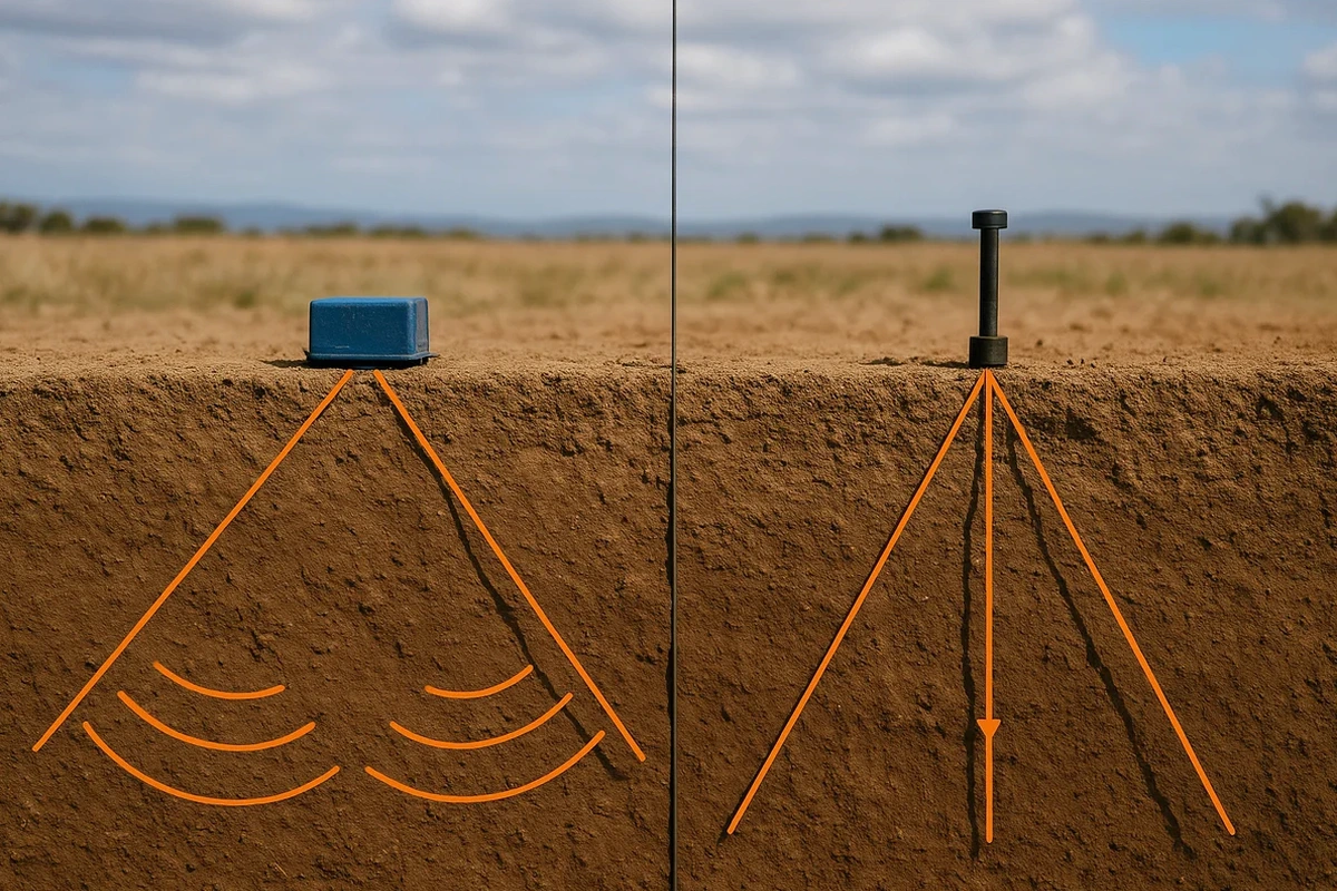
What is the difference between seismic refraction and reflection for locating abandoned mine shafts?
Seismic refraction is highly effective at detecting the low-velocity zone associated with collapsed or backfilled shafts because it images the velocity structure of the uppermost 20–40 metres, where most shaft-related anomalies occur. Seismic reflection is better suited to mapping deeper geological boundaries and fault planes that may control mine water pathways. For a comprehensive shaft survey, refraction is the primary tool and reflection is added when deep structural control is required.
Can the survey be performed on a sloping site in the Pennine foothills west of Barnsley?
Yes, the refraction spread is laid along the ground surface and the tomographic inversion algorithm handles topography explicitly by incorporating the elevation profile into the ray-tracing model. The resulting velocity cross-section is referenced to the actual ground surface, not a horizontal datum, so slope angles up to about 30 degrees are processed without introducing significant artefacts. Steeper slopes may require a shorter spread or a different survey orientation to maintain data quality.
What is the typical cost range for a seismic refraction tomography survey in the Barnsley area?
A standard single-spread refraction survey in the Barnsley area, including mobilisation, data acquisition with a 24-channel array, tomographic processing, and a BS 5930-compliant report, typically falls in the range of £2,380 to £4,500. The final cost depends on the spread length, source type, number of shot points, and whether a MASW or reflection component is added.
How do you interpret seismic velocity in terms of rock rippability for an excavation near Barnsley?
Rippability is assessed by correlating the P-wave velocity model with published charts — for example, the Caterpillar performance handbook or ISO/DIS 22475-3 classification — that relate seismic velocity to excavation difficulty. In Barnsley’s geology, velocities below 1,500 m/s generally indicate soil or heavily weathered rock that can be excavated by a D6-D7 dozer; 1,500–2,500 m/s suggests marginal ripping with a D8-D9; and above 2,500 m/s typically requires hydraulic hammering or blasting. The continuous tomographic image allows the contractor to map the ripping limit across the entire excavation footprint rather than relying on interpolation between boreholes.